


Automotive OBD2 diagnostic program development
2021-06-27
1, because TL718 has established a physical layer, data link layer and part of the application layer protocol for you, so as long as the OBD2 standard application layer protocol text, ISO15031-5 or SAE J1979 (the two protocols are the same content).
2. One set of TL718 diagnostic interface or self-built circuit with TL718 chip.
3, a home PC computer.
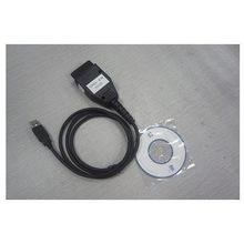
4, install the software: Accessport debugging software and VC++ (or VB, BC++, etc.) your favorite development software.
5, the symbol OBD2 standard car engine computer (or one car)
With these in mind, you can start developing your OBD2 standard program! ! !
TL718 basic information
TL718 communicates with single-chip microcomputer, PDA or PC RS232 through a UART serial port. On some new PCs, RS232 serial port is not equipped. It can communicate with TL718 through virtual serial port. For example, USB TO RS232, Ethernet TO RS232, or Bluetooth TO RS232 and many more.
------- RS232 ------ OBD2 cable ----------
| PC |<----------->| TL718|<------------>|Car Diagnostics |
------- ------ ----------
Regardless of the physical connection you use, you can use the HyperTerminal or serial debugging tools to send and receive characters directly from the keyboard. Before using the serial port debugging software, you must first set the correct COM port number and the correct baud rate. Typically 9600 baud (PIN6=0V), or 38400 baud (PIN6=VCC, PP OC default setting). The serial port is set to: 8 data bits, check digit: 0, stop bit 1 bit. If the setting is wrong, it will not be able to communicate normally with the TL718. All responses from TL718 end with a carriage return (0X0D) and an optional newline character (0X0A). Connect properly, after turning on the power. TL718 will drive the test LED light, (sparking 3 times), send:
TL718 starting
〉
If you receive the above information correctly, the serial port and connection settings are correct. The second line ">" symbol indicates that the TL718 is idle and can receive data from the RS232 immediately. If the 〉718 symbol is not received, the data is sent to the TL718, which may cause data loss. An incorrect response occurred. The format of the instruction sent by the PC from the serial port to the TL718:
TL718 has two formats of commands
1. The OBD connection command communicates with the vehicle.
2. Internal commands, all starting with AT, do not communicate with the vehicle .
This article refers to the address: http://
l Send ASCII characters that must end with 0x0d (carriage return). The characters following the carriage return are discarded by TL718.
l TL718 internal commands start with "AT" followed by visible characters. Invisible words with spaces are ignored.
l The OBD command can only contain hexadecimal ASCII codes (0-9, af, AF), and spaces are ignored.
l If the sent command cannot be effectively interpreted by TL718, TL718 will return a “?” indicating that the send command is invalid.
When the OBD l command processing TL718, TL718 continuous monitoring RTS and RS232 input pin, any one occurs, to interrupt the current OBD TL718 command, it returns quickly prompt ">", waits to receive a new command.
l Upper and lower case characters can be received by TL718, and spaces are ignored. The metaphor commands "ATZ", "atz", and "at z" are the same.
Analogy, we send a reset command to TL718 as long as the ASCII character "ATZ" + 0x0d (carriage return) is sent to the RS232 serial port;TL718 StartingNote: The ATZ command returns ELM327 V1.2 in order to use the off-the-shelf foreign OBD software, so this return message is used.
>ATZ
ELM327 v1.2
>
Return to the chip information with the "ATI" command.>ATIReturn the chip number with the "AT@S" command (this number is required to upgrade the hardware and provide warranty service)
TL718 v1.0
>>AT@S
CodeNumb
>
OBD command for TL718
If the command you send to TL718 starts with ASCII in hexadecimal number, TL718 considers it to be an OBD command. After receiving TL718, it converts the ASCII hexadecimal number into a single byte of hexadecimal data and sends it to the vehicle. Computer data bus. The OBD command is actually embedded in the data message packet and sent to the data bus. Most standards require that each data message packet contain a three-byte header and the last data check byte. The TL718 automatically adds these additional bytes. These default values do not need to be changed for the OBD2 diagnostic mode request instructions, but if you want to change these header byte values, you can change them with the internal command "ATSH XXXXXX".
Most OBD instructions are only one byte or two bytes long. The maximum length that TL718 allows to send is the byte specified by the standard. The excess will be discarded. The OBD command issued, can not appear a single number, hexadecimal numbers must be sent in pairs, metaphor 0 can not send a single "0", must send "00", if a single number appears, TL718 believes that the instruction format is wrong, will return One"?". Since OBD (Automotive Diagnostic Standard) uses hexadecimal, the data sent by the TL718 is also hexadecimal. The decimal value of the representative of Example 15 is 21;
After the OBD2 command is sent, the TL718 waits to receive the OBD message from the bus. If the address message is received and the address matches, the TL718 sends the data from the RS232 to the PC. If the message received by the TL718 does not match the sent address, then Ignore the message. However, the received message packet can also be viewed through the ATBD internal command. If the waiting time (the default value of P2MAX ATST command, default value 100ms) ends and no data of the matching address is received, TL718 returns "NO DATA", if the data is received and the address matches, the counting time is reset and waits until Waiting time overflows.
OBD2 standard diagnostic modeTo develop the OBD2 diagnostic program, you must master the nine diagnostic modes defined by ISO 15031-5 ( SAE J1979 ). For friends who are not very good in English, this site has a Chinese description:
Can refer to:
OBD system output information mode / serviceEach mode is followed by a parameter identifier (PID) indicating what parameters are followed. The PID 00 of each mode is a parameter defined by ISO15031. Each computer that conforms to the standard must support this parameter identification. Indicates whether this mode supports other PIDs.
- Mode 1: Request powertrain current data
- Mode 2: Request to freeze data
- Mode 3: Request emission related power system diagnostic trouble code
- Mode 4: Clear/Reset Emission Related Diagnostic Information
- Mode 5: Request oxygen sensor to monitor test results
- Mode 6: Request non-continuous monitoring system OBD test results
- Mode 7: Request continuous monitoring system OBD test results
- Mode 8: Request to control in-vehicle systems, tests or parts
- Mode 9: Read vehicle and calibration identification number
Communication with vehicle data
Format of the OBD2 command
1,
The above figure is the complete format of the message package of OBD2 diagnostic command (the most part of the vendor-specific function is also this format), TL718 can automatically set the Header/ID/PCI/CHECKSUM part of the data for the standard OBD2 diagnostic program. You almost don't have to care about modifying it. Want to know about the content, they are defined in the text defined by the ISO14230-2, J1850, IS9141-2 and ISO15765-2 data link layers.
TL718 automatically detects the physical connection of the data bus, can automatically search for the current vehicle protocol between protocols 1-9, and automatically returns data after the search. Of course, you can also manually set to a specific protocol. The TL718 does not search for the AF protocol because the AF protocol does not have a uniform ISO15031 application layer protocol like OBD2, so automatic search becomes meaningless.
2, ISO15031 (SAE J1979) is the application layer protocol, it also does not care about what physical layer protocol to use (TL718 automatic connection), you only need to send data when programming, and receive and process the received data (calculation or display) ). So with so many physical connections, the packets are sent and received in a unified standard, and our programming becomes relatively simple. Let's discuss the OBD2 instruction.
3, here we only need to care about the 7-byte data (data byte) part of the data message packet.
ISO15031-5 definition:
Byte Meaning 1 MODE represents the type of request data 2 PID parameter identification 3-7 According to different MODE and PID ISO15031-5 has a detailed definition
As shown in the figure above, connect the line and turn on the key to ON, do not start the vehicle. No need to make any settings, as long as you send instructions to TL718, TL718 automatically returns the data of the vehicle response.
Example 1: The figure shows: “0100” stands for ISO15031-5 to define the MODE 01 PID 00 instruction.
>01 00
41 00 BF 9F B9 90
The first byte 41 represents Mode 01 (01+40, standard definition)
The second byte 00 represents PID 00
3-6 bytes are the data sent back by the vehicle about the MODE 01 PID 00 request. The bit-defined data 1 of the other (PID01---PID32) flag supported by mode 00 indicates that support 0 means no support.
Example 2: Request (read) engine water temperature MODE 01 PID 05
We simply send the 0105 command to the vehicle >0105
41 05 7B
41 stands for MODE 01
05 stands for PID 05
7B is the water temperature value. The decimal value is (7*16+11)123. The water temperature is 123-40=80 degrees.
Example 3: Read engine speed rpm MODE 01 PID 0C
Also just send TL718: 010C
>01 0C
41 0C 1A F8
1AF8 is a 2-byte hexadecimal value, converted to a decimal number of 6904, 1/4 rpm per division
The speed is 6904/4=1726 rpm
Note: The conversion of the above data, and the format is defined in ISO15031-5


Read OBD2 DTCs Diagnostic Trouble Codes
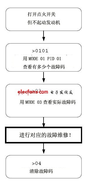
Reading the fault code is the most commonly used function of the diagnostic instrument. Here is a brief explanation. For details, please refer to the ISO15031-5 text. Under normal circumstances, you can directly read the current fault code with MODE 03, but here we
First use MODE 01 PID 01 to read how many fault codes are present in the ECU.
>01 01
41 01 81 07 65 04
>
41 01 The previous description of the response code for MODE 01 PID 01,
81 represents the current fault code number. This decimal value is 129, which does not mean that there are 129 fault codes.
81 Its highest bit MSB represents whether the fault light is lit, and the lower 7 bits represent the number of fault codes. The hexadecimal algorithm should be 0x81 & 0x7F = 0x01 so it is a fault code. Also, the decimal value is directly reduced by 128.
Namely: 129-128=1;
So 81 stands for, the fault light is on, there is a fault code, please refer to the standard text for the data behind 81, and it does not matter if the fault code is read.
In this example, TL718 only returns one row of data, but if there are additional control modules that also support the response condition, it is possible to return multiple rows of information.
Common analogy: When the engine computer and the automatic gearbox control computer return information at the same time, there will be 2 lines of information. To confirm which computer returns which line of information, you must set the 3-byte header to return the OBD message (AT H1). The internal command is opened), and the third byte (source address) in the header byte of the message is determined to be the message packet returned by that computer module. I will not discuss it here, but I will discuss it in detail in the other chapters.
Now that you have read how many fault codes there are, what are the actual fault codes?
Read with OBD2 diagnostic mode MODE 03: simply send 03 to TL718
>03
Possible return information data is as follows:
43 01 33 00 00 00 00
Note: If the number of fault codes is more than 3 or more computer modules, a multi-line message packet will be returned.
43 is the response to the MODE 03 request (03+40), the other 6 bytes are the fault code, and 2 bytes represent a fault code.
Here are three data representing the fault code, "0000" is the fill data returned by ISO15031 in this mode is not the actual fault code.
Fault code meaning: ISO definition: The first number of the two-byte fault code (example 0133) is shown in the following table. Now analyze the above fault code 0133:
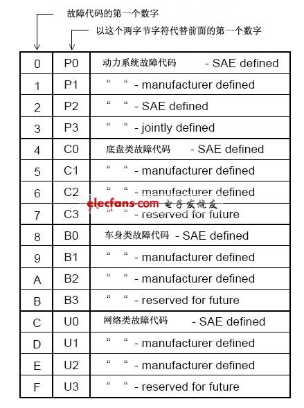
The first digit "0" is replaced by "P0" according to the above table. 0133 represents the fault code P0133.
Similarly, if D016 is received, "D" is replaced by U1, then the fault code is U1016;
If the receipt is 1131, the fault code is P1131.
Note: The ISO15765 CAN fault code message packet is slightly different from the information returned by J11850 and ISO9141 ISO14230.
When writing a program, note that the information returned by ISO 15765 represents the number of fault codes (DTCs) in the computer module.
See the definition in ISO15031-5 for details.
Clear fault code
The OBD2 diagnostic mode MODE04 is a function of the reset ECU, and also clears the fault code; after execution, the ECU will:
1. The number of reset fault codes is 0.
2. Delete all fault codes 3. Delete stored frozen data 4. Delete all O2 sensors to listen to test data 5. Delete data information of mode MODE06 and MODE 07
After resetting your car, due to resetting some data, it may cause abnormal operation in a short time. In order to prevent accidental reset of the ECU,
ISO15031-5 requires all scanning tools (diagnostics) to add a "confirmation message" before sending the MODE 04 command.
The TL718 does not monitor whether the content of the transmitted message is a reset command.
>04
44
>
After sending the 04 command, the vehicle ECU receives the attack and will immediately reset the above content.
Concurrently send back a response message 44 (04+40) of MODE 04.
General process:
Conclusion
- ISO14230 ISO9141 requires an initialization process before communication and a periodic handshake signal after connection. These TL718s have been automatically completed, and the OBD2 standard diagnostics are not changed. How to change these parameters:
- After reading this, you can start your OBD2 development. In fact, the vendor-specific diagnostic function is almost as simple as that. Why is it called private because it does not expose the application layer protocol. How much process is developed during development than our OBD2. It is how to use the TL718 to read a dedicated diagnostic command (that is, an application layer protocol) from a dedicated device. Discuss this issue in a Diagnostic Tool that develops dedicated functions.
- The other diagnostic modes of OBD2 are not explained here, and the diagnostic methods are the same. See ISO15031-5 or SAE J1979 for details.
- Try more and more, you will find that developing diagnostic programs is so simple.
We make OBD connector with terminal by ourselves, soldering type and crimping type are both available. Also 12V and 24V type. OBD1, OB2, J1939, J1708, J1962, etc. Also molded by different type, straight type or right-angle type. The OBD connector cables used for Audi, Honda, Toyota, BWM, etc. We have wide range of materials source , also we can support customers to make a customized one to replace the original ones.
Vehicle Diagnostic Cables, Diagnostic OBD Cable, OBD2 Splitter Y Cables, OBD2 Diagnostic Adapters, OBD Heavy Vehicle Cables
ELM327 Auto Code Reader Co., Ltd. http://www.wireharness-assembling.com