

Design of Automobile OBD General Fault Diagnosis Instrument Based on R8C
2021-06-27
0 Introduction On-Board Diagnostics (OBD) has the function of identifying the area where a fault may exist, and stores the information in the memory of the ECU (Electronic Control Unit) in the form of a fault code, through the OBD fault diagnosis instrument. The fault code and related information stored in the in-vehicle ECU can be read out to facilitate vehicle management and maintenance. The OBD system was originally proposed to control the growing problem of automotive pollution, originating from the 1982 CARB emission regulations, and subsequently implementing the new OBD II requirements in 1996. In 2001, the European Community also required European cars produced by automakers in Europe to be equipped with the European On-board Diagnosis System (EOBD). In China, in April 2005, the State Environmental Protection Administration and the General Administration of Quality Supervision, Inspection and Quarantine jointly promulgated GB18352.3-2005 ((Light Vehicle Pollutant Limits and Measurement Methods (China III, IV Phase)), referred to as “Country III, IV". According to the requirements of the National III, the first type of gasoline vehicles (the M1 vehicles with a total number of seats not exceeding 6 and the maximum total mass not exceeding 2 500 kg) are required to be equipped with the OBD system from July 1, 2008. Performed synchronously with the vehicle compliance check.
Based on the requirements of GB18352.3 for OBD system and fault diagnosis device, based on the full study of ISO and SAE related OBD standards and communication protocols, this paper designs a car based on Renesas R8C microcontroller R5F21237. OBD general fault diagnosis instrument. The diagnostic device is compatible with all communication protocols specified in GB18352.3 and can diagnose all diagnostic services specified in ISO 15031-5 with low cost and portability.
1 Requirements for automotive OBD general fault diagnostic equipment According to the requirements of GB18352.3, external diagnostic equipment communicating with the vehicle OBD system must comply with ISO 15031-4 "Road vehicles - communication between vehicles and emissions related external diagnostic equipment" Part: Requirements for External Fault Diagnosis Equipment Requirements. These requirements mainly include four aspects: unified diagnostic connector, compatible communication protocol, standard fault code and diagnostic service range.
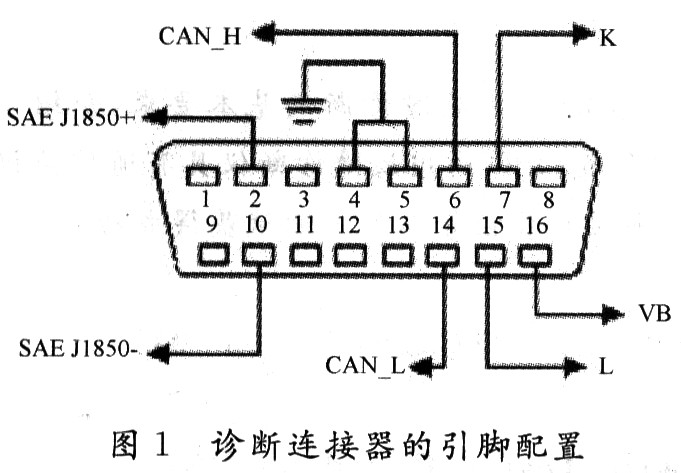
1.1 Diagnostic Connector
The connector between the OBD Universal Fault Diagnosis Tool and the vehicle uses a unified diagnostic connector. The pin configuration definition is shown in Figure 1. The undefined pins can be reserved for later use by the diagnostic device.
This article refers to the address: http://
1.2 Communication Protocol
The communication protocols that can be used in the communication system between the OBD general-purpose fault diagnosis instrument and the vehicle are ISO 9141, SAE J1850 41, 6 Kb/sPWM (pulse width modulation), SAEJ1850 10, 4 Kb/s VPW (variable pulse width), ISO 14230 (KW 2000), ISO 15765-4 (CAN), SAE J1939-73 (CAN). According to SAE J1978 or ISO15031-5, only one communication protocol is allowed for any vehicle. In order to be compatible with OBD systems of various models, the automotive universal fault diagnosis instrument must support all the above protocols.
1.3 Diagnostic Service Scope The vehicle general fault diagnosis diagnostics includes nine service modes. The details are as follows:
The purpose of reading current power system diagnostic data is to obtain emission-related data values, including analog inputs, outputs, digital inputs, outputs, and system status information.
The purpose of reading the system freeze frame is to collect freeze frames associated with power system emissions and other system freeze frames for the manufacturer's special needs. Read the diagnostic trouble code The Automotive General Fault Diagnostics obtains the general diagnostic trouble code for each vehicle system.
Clear/Reset Emission-Related Diagnostic Information The Automotive General-Purpose Troubleshooter provides a means of clearing the vehicle's ECUs for fault diagnosis information. These fault diagnosis information includes: the number of diagnostic fault codes, diagnostic fault codes, fault codes of frozen frame data, freeze frame data, status of system monitoring test, vehicle monitoring test results, mileage traveled when MIL is activated, and warm-up after DTC clearing The number of times, the mileage after the DTC is cleared, the time the engine is running when the MIL is activated, the time after the diagnosis of the fault code is cleared, and other record information defined by other manufacturers.
Reading the oxygen sensor monitoring test result The automobile general fault diagnostic instrument obtains the monitoring result of the vehicle oxygen sensor monitoring.
Read the monitoring test results of the special monitoring system of the vehicle. The vehicle general fault diagnostic instrument obtains the on-board diagnostic monitoring test results of the discontinuous monitoring of special components/systems. For example, catalyst monitoring and evaporation monitoring systems.
Reading the emission-related diagnostic trouble code detected during the current or most recent driving The vehicle general diagnostic troubleshooter obtains a diagnostic trouble code detected during the current or most recent driving. The purpose is to help the service technician to obtain the test repair effect through a single driving cycle after the vehicle is repaired or after the diagnostic information is cleared.
The purpose of reading the onboard system, test or component is to allow the automotive universal fault diagnostic device to control the operation of the onboard system, test or component.
Reading Vehicle Information The vehicle general fault Diagnostic Tool can request vehicle information describing the vehicle, such as a vehicle identification number and a calibration ID.
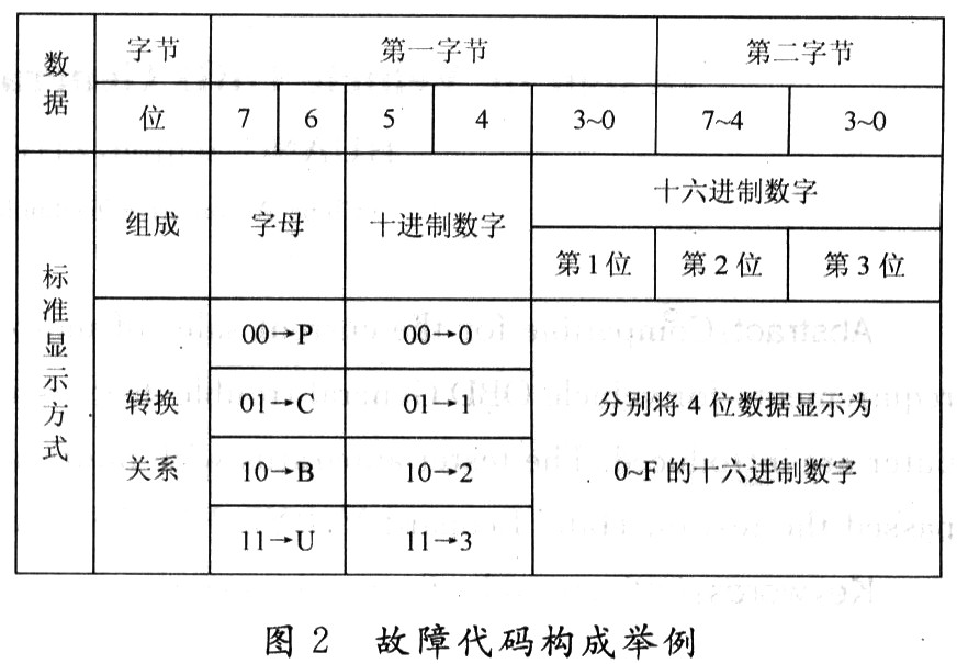
1.4 Diagnostic Trouble Code (DTCs_Diagnostic Trouble Code) Display The OBD diagnostic trouble code read by the general-purpose fault diagnosis tool consists of two bytes. It should be displayed as 1 letter + 1 digit decimal digit + 3 digits hexadecimal. The standard display mode of the number is displayed. The conversion relationship between the read two-byte data to the standard display mode is as shown in FIG. 2. DTCs are divided into four categories according to the initial letters, where B is the body type DTCs, C is the chassis type DTCs, P is the power class DTCs, and U is the network class DTCs.
2 Design of automobile universal fault diagnosis instrument
2.1 Hardware Design of the System The hardware part of the design is mainly divided into four modules. The hardware structure diagram is shown in Figure 3.

The MCU module is the core part of the whole hardware system, including a Renesas R8C series MCU R5F21237JPF and some peripheral circuits, which undertake the task of computing and processing signals. The module is respectively connected with the keyboard module, the liquid crystal display module and the communication module, and performs information interaction with the three modules.
R5F21237JPF belongs to Renesas R8C/Tiny series of microcontrollers. This design uses two 8-bit multi-function timers of R5F21237JPF for system timing control. It uses two serial ports to drive MC33390 and ST-L9637, and uses its CAN. The controller drives the TJA1050 for communication; 11 input/output ports are used to connect the keyboard module; 2 KB RAM and 64 KB program flash are used to write the embedded program, and the parallel port 2 is used to communicate with the LCD.
The LCD screen adopts COMJ4×8C, which is a 128×64 graphic dot matrix liquid crystal screen, which can display 8×4 (16×16 dot matrix) Chinese characters, and can also display graphics and characters. The data latch is displayed with simple operational instructions. The main function of this module is to display the function menu, fault name and so on.
The core of the keyboard module is a 3×8 keypad array. The 3 columns and 8 rows are respectively connected to the single chip through 11 pins. The keyboard keys include 10 numeric keys, page change keys, line feed keys, determination and cancel keys, and the like. The communication module is the interface between the diagnostic instrument and the vehicle ECU. It is mainly composed of ST-L9637, MC33390 and TJA1050. ST-L9637 implements ISO 9141, ISO 14230 (KW 2000) protocol; MC33390 implements SAE J1850 41, 6 Kb/s PWM. , SAEJ1850 10, 4 Kb / s VPW protocol; TJA1050 implements ISO 15765-4 (CAN), SAE J1939-73 (CAN) protocol. The vehicle ECU is connected to the single-chip microcomputer through these chips. This part of the circuit is slightly complicated and the role is very important. It is the key to the diagnostic instrument meeting all the communication protocols required by ISO15031 and SAEJ1978.
2.2 Software Design The software structure diagram of this design is shown in Figure 4.
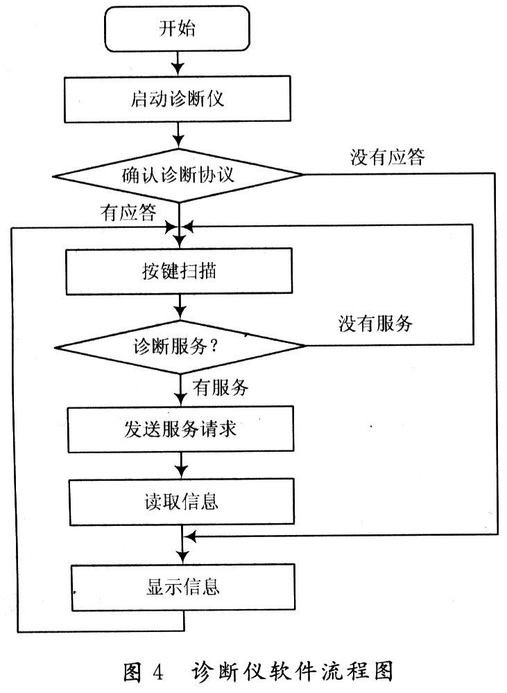
(1) Starting the diagnostic instrument When the fault diagnosis is turned on, the vehicle ignition key is placed in the ON position, and the vehicle supplies power to the diagnostic instrument. After the power is turned on, the initial parameters of the diagnostic device are set under the control of R5F21237JPF.
(2) Confirmation of the diagnostic protocol The protocol confirmation data is sent to the vehicle diagnostic interface after the diagnosis is completed. Diagnostic protocol for each connector that complies with the SAE J1962 Vehicle Fault Diagnosis Interface (including ISO9141, ISO 14230 (KW 2000), SAE J1850 41, 6 Kb/sPWM, SAE J1850 10, 4 Kb/s VPW , ISO 157654, SAE J193973) The pin sends the protocol confirmation command one by one. If a correct response is received in an acknowledgment, the communication is confirmed to use the protocol; if the acknowledgment command to send a protocol does not answer or the acknowledgment is none, the troubleshooter sends a confirmation command for the next protocol; if it continues for 5 consecutive cycles After the confirmation command of each protocol is sent, the correct response is still not received, and the fault diagnosis tool issues an error warning.
(3) Keyboard scanning In this design, the keyboard scanning adopts the method of timing scanning. The keyboard is scanned every 50 ms. If a key press is detected, the calculation operation is a display operation operation or a service type of diagnosis.
(4) Diagnostic service If the service mode requested by the troubleshooter is confirmed by the keyboard scanner, the request for the service is sent and the corresponding response information is read. Diagnostic services play a vital role in this design, enabling information interaction between the diagnostic instrument and the ECU.
(5) Display content The display module contains all subroutines related to the liquid crystal display, displays menus, displays fault contents, and displays warning information. Through the button operation, the selection display menu is used to select the operation service of the diagnostic device and select the display content; if more than one page is displayed when the fault content is displayed, the page can be turned by the "previous page" and "next page" keys, and the page is pressed. The Cancel button returns to the previous directory; the warning message displays a warning message when the communication protocol fails or the diagnostic service fails. The warning message is automatically displayed when the operation fails.
3 Conclusions
This paper describes the basic requirements of automotive OBD general fault diagnosis according to the requirements of GB18352.3-2005, and introduces a hardware and software design scheme based on Renesas R8C microcontroller. The advantage of this solution is that it can be compatible with various OBD diagnostic communication protocols, Chinese display interface, low cost and convenient operation. Tested on Hafei Saibao V, BYD F6 and Chevrolet Cruze, the diagnostic instrument is stable, easy to operate and strong in anti-interference ability. With the gradual implementation of the relevant regulations of OBD in China, the software and hardware design of the diagnostic instrument will have broad application prospects.
We make OBD connector with terminal by ourselves, soldering type and crimping type are both available. Also 12V and 24V type. OBD1, OB2, J1939, J1708, J1962, etc. Also molded by different type, straight type or right-angle type. The OBD connector cables used for Audi, Honda, Toyota, BWM, etc. We have wide range of materials source , also we can support customers to make a customized one to replace the original ones.
Sae J1708 Connector, Sae J1939 Connector, OBD2 Diagnostic Connectors, Diagnostic Connector, Deutsch Diagnostic Connector
ELM327 Auto Code Reader Co., Ltd. http://www.oemwireharness.com